
ILMcom USB Interface
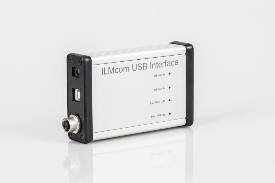
The ILMcom USB Interface is used to connect an RS485 sensor bus to a PC with a USB interface and thus enables IL Metronic digital sensors to be read out and configured.
GENERALS
The ILMcom interface is used for the wired, digital communication of the sensor components and evaluating instruments of the company IL Metronic Sensortechnik GmbH. The interface bases on a differential, serial data transmission according to RS485 half-duplex standard for the hedge of an undisturbed connection over a long distance. The standard signal level amounts 5V, thereby the voltage is tolerated until 12V.
The communication protocol ILMcom is inspired by MODBUS® RTU standard, which is widespread in the industry. Thus, a simultaneous operation with corresponding components on a common bus will be possible. The 19200-baud rate, the 8 data bits, 1 stop bit and an even parity (8E1) are intended as interface parameters. The ILMcom protocol is a single master protocol. This master controls the complete transmission and supervises the actual possible occurring timeouts (no answer from the addressed device). The connected devices may send telegrams only after the request from the master.
GENERAL FRAME STRUCTURE
| Device address | Function | Data/Parameter | CRC-checksum |
|---|---|---|---|
| 1 Byte | 1 Byte | n Byte | 2 Byte |
In principal, the sent (Master -> Slave) and received frames (Slave -> Master) are even structured.
A break of at least 3,5 signs, which serve as a stop condition for the individual bus subscriber and select so the end of a data frame, must be kept between two consecutive frames.
The device address indicates, which bus subscriber should be addressed and from which device comes an answer. The addresses are permitted from 0x01 until 0x7F.
The function code represents the performed command and is transmitted to the master at the appropriate answer too. The ILMcom protocol uses principal the sector from 0x41 until 0x48, which is reserved for user-defined functions in the MODBUS® standard.
| Functions code | Function | Answer | Interpretation |
|---|---|---|---|
| 0x41* | ReadUV | 0x0000…0xFFFF | UV irradiance |
| 0x42* | ReadTemp | 0x00…0xFF | Sensor temperature [°C] |
| 0x43* | ReadRange | 0x0000…0xFFFF | UV measurement range |
| 0x44* | ReadSerial | 8 Byte, ASCII | Sensor serial number |
| 0x45* | ReadUvEndValue | 0x0000…0xFFFF | UV measurement range [W/m²] |
The unit of the UV irradiance can be chosen customized. As standard, a readout of 60000 equals the maximum UV intensity which is engraved on the sensor body.
The master would send the following telegram for retrieving the sensor temperature of sensor 0x40, for example:
| Device address | Function | CRC-checksum |
|---|---|---|
| 0x40 | 0x42* | 0xF183 |
In this case, the answer of the slave would be, for example:
| Device address | Function | Data | CRC-checksum |
|---|---|---|---|
| 0x40 | 0x42* | 0x22 | 0xC0AD |
Therefore, the measured sensor temperature is 34°C.
Later the calculation of the CRC-checksum is described separate.
In addition, the MODBUS® function DIAGNOSTICS with the function code 0x08 is available. The sent telegram is transmitted back just the same. In this way, an easy connection test can be performed.
SPECIAL FRAMES
A special frame structure is provided for functions, which intervene in the sensor configuration to write. First, the password-protected user configuration mode must be activated for access to these functions. The password serves the protection against accidental change of the sensor configuration and is 0x1234* in general. A customized password change is possible ex works.
| Function | Password | CRC-checksum |
|---|---|---|
| 0x46* | 0x1234 | 2 Byte |
In this case, the answer of the slave is designed as already described. Thereby, the data byte 0x00 is appended after the function code to acknowledge a successful activation.
The master would send the following telegram for activating the user configuration mode of the sensor 0x40, for example:
| Device address | Function | Password | CRC-checksum |
|---|---|---|---|
| 0x40 | 0x46* | 0x1234 | 0xF946 |
In this case, the answer of the slave would be, for example:
| Device address | Function | Data | CRC-checksum |
|---|---|---|---|
| 0x40 | 0x46* | 0x00 | 0x4274 |
If the user configuration mode was activated once, the configuration command is available until to the next deactivation and restarting of the sensor supply voltage.
| Function code | Function | Parameter | Interpretation |
|---|---|---|---|
| 0x47* | SetAdress | 0x01…0xFF | New sensor address |
| 0x48* | UserCalHi | 0x0000…0xFFFF | Upper calibration point |
| 0x49* | UserCalLo | 0x0000…0xFFFF | Lower calibration point |
A standard data frame is used to set a new bus address. In this case, the answer of the slave is built as already described. Thereby the new address is already used. The data byte 0x00 is appended after the function code to acknowledge a successful change of the address.
The functions UserCalHi and UserCalLo realize a correction possibility of the UV measurement value by the customer in form of a two-point calibration. For this purpose, the sensor must be exposed to the appropriated reference irradiation and then the appropriated calibration function must be retrieved. Thereby, it should be noted, that the both chosen calibration points should be as far away from each other as possible. Thus, the irradiance intensity for the lower calibration point should be set to zero (darkened sensor), during a highest-possible irradiance intensity, which is close to the measuring range final value, is useful for the upper calibration point. The reference irradiance must be applied at least 3 seconds before and after the call of a calibration function. Also, it should be note, that both calibration points must be set generally for a successful calibration. Both calibration functions are acknowledged with a standard frame and a data byte 0x00 after a successful performance.
Additional configuration possibilities can be realized customized upon request.
The master would send the following telegram to change the sensor address from the sensor 0x40 to 0x50, e.g.:
| Device address | Function | New address | CRC-checksum |
|---|---|---|---|
| 0x40 | 0x47* | 0x50 | 0x43D8 |
In this case, the answer of the slave would be, for example:
| Device address | Function | Data | CRC-checksum |
|---|---|---|---|
| 0x50 | 0x47* | 0x00 | 0x4221 |
The calibration would correspond to the following procedure, for example:
- Darken sensor and wait at least 3 seconds.
- Set the lower calibration point
| Device address | Function | Data | CRC-checksum |
|---|---|---|---|
| 0x40 | 0x49* | 0x0000 | 0xC432 |
- Wait for the acknowledgement of the sensor. This is:
| Device address | Function | Data | CRC-checksum |
|---|---|---|---|
| 0x40 | 0x49* | 0x00 | 0x4784 |
- Sensor exposes to the reference irradiance. A measurement value of 5000 (0xC350) should be achieved at an irradiance intensity of 5W/m².
Wait 3 seconds. - Set the higher calibration point
| Device address | Function | Data | CRC-checksum |
|---|---|---|---|
| 0x40 | 0x48* | 0xC350 | 0xC53E |
- Wait for the acknowledgement of the sensor. This is:
| Device address | Function | Data | CRC-checksum |
|---|---|---|---|
| 0x40 | 0x48* | 0x00 | 0x4614 |
- Check the success of the calibration.
ERROR HANDLING
If an irregularity is determined from an ILMcom slave during communication, this is showed in his answer on the master. For this purpose, the most significant bit of the function code is set and an error code (1 byte) is transmitted in the data section of the frame. Possible errors are:
| Error code | Importance |
|---|---|
| 0x01 | Unknown function code |
| 0x02 | CRC-error |
| 0x03 | Values outside of the range |
Incorrect function calls are rejected after the acknowledgment and are not processed further. If parity or timing errors appearance by function calls, the completely frame is rejected and is not acknowledged for the prevention of collisions in incorrect addressing.
CRC-CALCULATION
The calculation of the CRC-checksum happens over all the other sign of the frame. Then the least significant byte is on the second last and the most significant byte is transmitted on the last position of the telegram.
The relevant receiver of a telegram calculates the checksum again and compares it with the received checksum.
The calculation algorithms correspond to the CRC16 standard using the generator polynomial 0xA001 (or 0x8005 in reversed representation) and the CRC-start value 0xFFFF.